Bestsellers
-
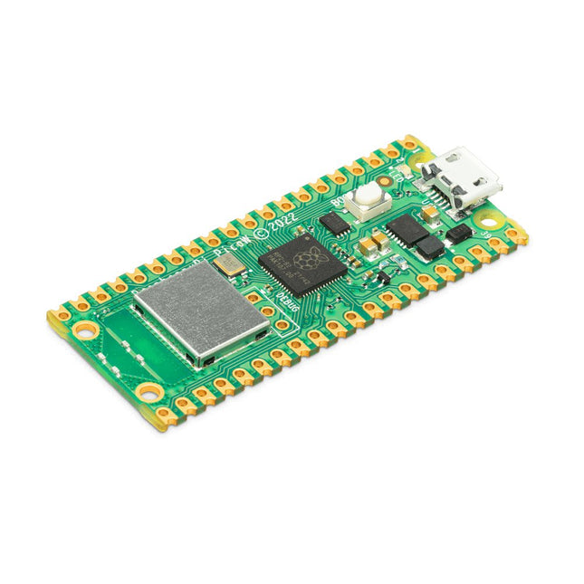
Raspberry Pi Foundation Raspberry Pi Pico W
Raspberry Pi Pico W is a microcontroller board based on the Raspberry Pi RP2040 microcontroller chip. The RP2040 microcontroller chip ('Raspberry Silicon') offers a dual-core ARM Cortex-M0+ processor (133 MHz), 256 KB RAM, 30 GPIO pins, and many other interface options. In addition, there is 2 MB of on-board QSPI flash memory for code and data storage. Raspberry Pi Pico W has been designed to be a low cost yet flexible development platform for RP2040 with a 2.4 GHz wireless interface using an Infineon CYW43439. The wireless interface is connected via SPI to the RP2040. Features of Pico W RP2040 microcontroller with 2 MB of flash memory On-board single-band 2.4 GHz wireless interfaces (802.11n) Micro USB B port for power and data (and for reprogramming the flash) 40 pin 21 x 51 mm 'DIP' style 1 mm thick PCB with 0.1' through-hole pins also with edge castellations Exposes 26 multi-function 3.3 V general purpose I/O (GPIO) 23 GPIO are digital-only, with three also being ADC capable Can be surface mounted as a module 3-pin ARM serial wire debug (SWD) port Simple yet highly flexible power supply architecture Various options for easily powering the unit from micro USB, external supplies or batteries High quality, low cost, high availability Comprehensive SDK, software examples and documentation Features of the RP2040 microcontroller Dual-core cortex M0+ at up to 133 MHz On-chip PLL allows variable core frequency 264 kByte multi-bank high performance SRAM External Quad-SPI Flash with eXecute In Place (XIP) and 16 kByte on-chip cache High performance full-crossbar bus fabric On-board USB1.1 (device or host) 30 multi-function general purpose I/O (four can be used for ADC) 1.8-3.3 V I/O voltage 12-bit 500 ksps analogue to digital converter (ADC) Various digital peripherals 2x UART, 2x I²C, 2x SPI, 16x PWM channels 1x timer with 4 alarms, 1x real time clock 2x programmable I/O (PIO) blocks, 8 state machines in total Flexible, user-programmable high-speed I/O Can emulate interfaces such as SD card and VGA Note: Raspberry Pi Pico W I/O voltage is fixed at 3.3 V. Downloads Datasheet Specifications of 3-pin Debug Connector
€ 7,95
Members identical
-
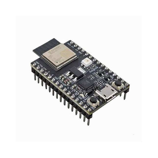
Espressif ESP32-C3-DevKitM-1
ESP32-C3-DevKitM-1 is an entry-level development board based on ESP32-C3-MINI-1, a module named for its small size. This board integrates complete Wi-Fi and Bluetooth LE functions. Most of the I/O pins on the ESP32-C3-MINI-1 module are broken out to the pin headers on both sides of this board for easy interfacing. Developers can either connect peripherals with jumper wires or mount ESP32-C3-DevKitM-1 on a breadboard. Specifications ESP32-C3-MINI-1 ESP32-C3-MINI-1 is a general-purpose Wi-Fi and Bluetooth LE combo module that comes with a PCB antenna. At the core of this module is ESP32-C3FN4, a chip that has an embedded flash of 4 MB. Since flash is packaged in the ESP32-C3FN4 chip, rather than integrated into the module, ESP32-C3-MINI-1 has a smaller package size. 5 V to 3.3 V LDO Power regulator that converts a 5 V supply into a 3.3 V output. 5 V Power On LED Turns on when the USB power is connected to the board. Pin Headers All available GPIO pins (except for the SPI bus for flash) are broken out to the pin headers on the board. For details, please see Header Block. Boot Button Download button. Holding down Boot and then pressing Reset initiates Firmware Download mode for downloading firmware through the serial port. Micro-USB Port USB interface. Power supply for the board as well as the communication interface between a computer and the ESP32-C3FN4 chip. Reset Button Press this button to restart the system. USB-to-UART Bridge Single USB-UART bridge chip provides transfer rates up to 3 Mbps. RGB LED Addressable RGB LED, driven by GPIO 8. Downloads ESP32-C3 Datasheet ESP32-C3-MINI-1 Datasheet ESP32-C3-DevKitM-1 Schematic ESP32-C3-DevKitM-1 PCB Layout ESP32-C3-DevKitM-1 Dimensions
€ 19,95
Members € 17,96
-
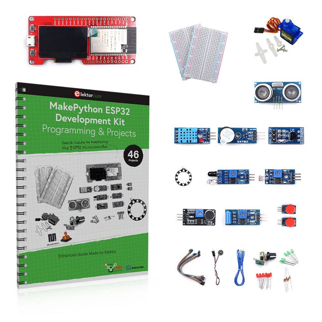
Elektor Bundles MakePython ESP32 Development Kit
Learn how to use the ESP32 Microcontroller and MicroPython programming in your future projects! The project book, written by well-known Elektor author Dogan Ibrahim, holds many software- and hardware-based projects especially developed for the MakePython ESP32 Development Kit. The kit comes with several LEDs, sensors, and actuators. The kit will help you acquire the basic knowledge to create IoT projects. The book’s fully evaluated projects feature all the supplied components. Each project includes a block diagram, a circuit diagram, a full program listing, and a complete program description. Included in the kit 1x MakePython ESP32 development board with color LCD 1x Ultrasonic ranging module 1x Temperature and humidity sensor 1x Buzzer module 1x DS18B20 module 1x Infrared module 1x Potentiometer 1x WS2812 module 1x Sound sensor 1x Vibration sensor 1x Photosensitive resistance module 1x Pulse sensor 1x Servo motor 1x USB cable 2x Button 2x Breadboard 45x Jumper wire 10x Resistor 330R 10x LED (Red) 10x LED (Green) 1x Project book (206 pages) 46 Projects in the Book LED Projects Blinking LED Flashing SOS Blinking LED – using a timer Alternately flashing LEDs Button control Changing the LED flashing rate using pushbutton interrupts Chasing-LEDs Binary-counting LEDs Christmas lights (random-flashing 8 LEDs) Electronic dice Lucky day of the week Pulsewidth Modulation (PWM) Projects Generate a 1000-Hz PWM waveform with 50% duty cycle LED brightness control Measuring the frequency and duty cycle of a PWM waveform Melody maker Simple electronic organ Servo motor control Servo motor DS18B20 thermometer Analog To Digital Converter (ADC) Projects Voltmeter Plotting the analog input voltage ESP32 internal temperature sensor Ohmmeter Photosensitive resistance module Digital To Analog Converter (DAC) Projects Generating fixed voltages Generating a sawtooth-wave signal Generating a triangular-wave signal Arbitrary periodic waveform Generating a sinewave signal Generating accurate sinewave signal using timer interrupts Using The OLED Display Seconds counter Event counter DS18B20 OLED based digital thermometer ON-OFF temperature controller Measuring the temperature and humidity Ultrasonic distance measurement Height of a person (stadiometer) Heart rate (pulse) measurement Other Sensors Supplied with the Kit Theft alarm Sound-activated light Infrared obstacle avoidance with buzzer WS2812 RGB LED ring Timestamping temperature and humidity readings Network Programming Wi-Fi scanner Remote control from the Internet browser (using a smartphone or PC) – Web Server Storing temperature and humidity data in the Cloud Low-Power Operation Using a timer to wake up the processor
€ 89,95€ 59,95
Members identical
-
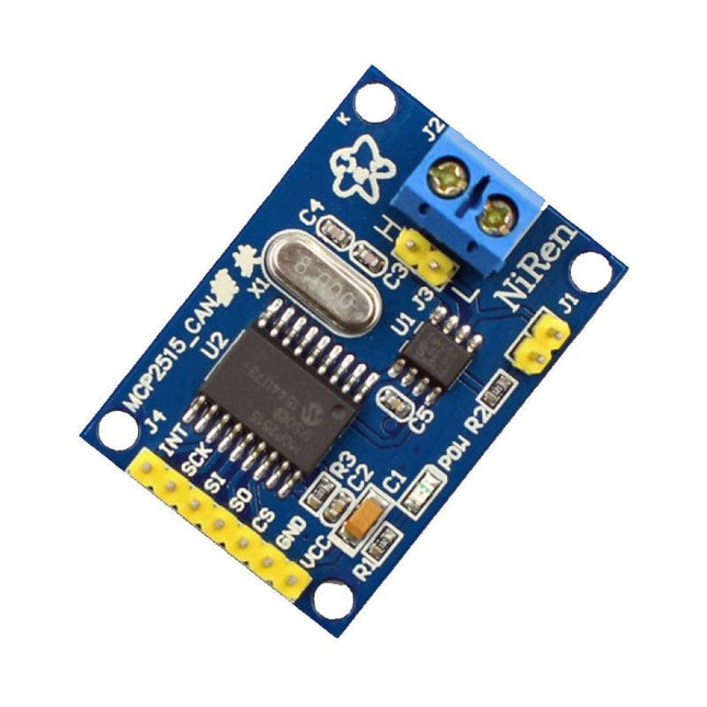
Makerfabs CAN Module MCP2515
This CAN Module is based on the CAN bus controller MCP2515 and CAN transceiver TJA1050. With this module, you will easy to control any CAN Bus device by SPI interface with your MCU, such as Arduino Uno and so on. Features Support CAN V2.0B Communication rate up to 1 MB/s Working Voltage: 5 V Working Current: 5 mA Interface: SPI Downloads MCP2515 Datasheet TJA1050 Datasheet
€ 9,95
Members € 8,96
-
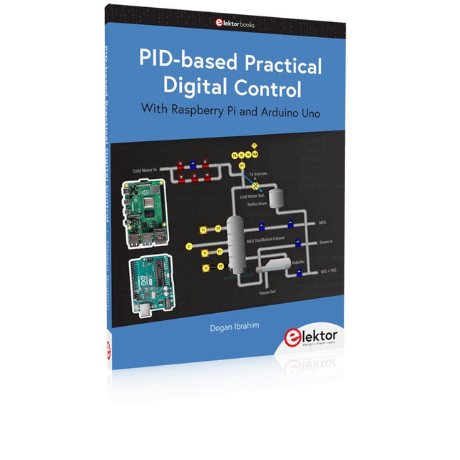
Elektor Publishing PID-based Practical Digital Control with Raspberry Pi and Arduino Uno
The Arduino Uno is an open-source microcontroller development system encompassing hardware, an Integrated Development Environment (IDE), and a vast number of libraries. It is supported by an enormous community of programmers, electronic engineers, enthusiasts, and academics. The libraries in particular really smooth Arduino programming and reduce programming time. What’s more, the libraries greatly facilitate testing your programs since most come fully tested and working. The Raspberry Pi 4 can be used in many applications such as audio and video media devices. It also works in industrial controllers, robotics, games, and in many domestic and commercial applications. The Raspberry Pi 4 also offers Wi-Fi and Bluetooth capability which makes it great for remote and Internet-based control and monitoring applications. This book is about using both the Raspberry Pi 4 and the Arduino Uno in PID-based automatic control applications. The book starts with basic theory of the control systems and feedback control. Working and tested projects are given for controlling real-life systems using PID controllers. The open-loop step time response, tuning the PID parameters, and the closed-loop time response of the developed systems are discussed together with the block diagrams, circuit diagrams, PID controller algorithms, and the full program listings for both the Raspberry Pi and the Arduino Uno. The projects given in the book aim to teach the theory and applications of PID controllers and can be modified easily as desired for other applications. The projects given for the Raspberry Pi 4 should work with all other models of Raspberry Pi family. The book covers the following topics: Open-loop and closed-loop control systems Analog and digital sensors Transfer functions and continuous-time systems First-order and second-order system time responses Discrete-time digital systems Continuous-time PID controllers Discrete-time PID controllers ON-OFF temperature control with Raspberry Pi and Arduino Uno PID-based temperature control with Raspberry Pi and Arduino Uno PID-based DC motor control with Raspberry Pi and Arduino Uno PID-based water level control with Raspberry Pi and Arduino Uno PID-based LED-LDR brightness control with Raspberry Pi and Arduino Uno
€ 39,95
Members € 35,96
-
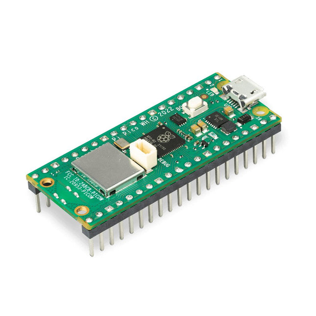
Raspberry Pi Foundation Raspberry Pi Pico WH
Raspberry Pi Pico WH is a microcontroller board based on the Raspberry Pi RP2040 microcontroller chip. The RP2040 microcontroller chip ('Raspberry Silicon') offers a dual-core ARM Cortex-M0+ processor (133 MHz), 256 KB RAM, 30 GPIO pins, and many other interface options. In addition, there is 2 MB of on-board QSPI flash memory for code and data storage. Raspberry Pi Pico WH has been designed to be a low cost yet flexible development platform for RP2040 with a 2.4 GHz wireless interface using an Infineon CYW43439. The wireless interface is connected via SPI to the RP2040. Features of Pico WH RP2040 microcontroller with 2 MB of flash memory On-board single-band 2.4 GHz wireless interfaces (802.11n) Micro USB B port for power and data (and for reprogramming the flash) 40 pin 21 x 51 mm 'DIP' style 1 mm thick PCB with 0.1' through-hole pins also with edge castellations Exposes 26 multi-function 3.3 V general purpose I/O (GPIO) 23 GPIO are digital-only, with three also being ADC capable Can be surface mounted as a module 3-pin ARM serial wire debug (SWD) port Simple yet highly flexible power supply architecture Various options for easily powering the unit from micro USB, external supplies or batteries High quality, low cost, high availability Comprehensive SDK, software examples and documentation Pre-populated headers and 3-pin debug connector Features of the RP2040 microcontroller Dual-core cortex M0+ at up to 133 MHz On-chip PLL allows variable core frequency 264 kByte multi-bank high performance SRAM External Quad-SPI Flash with eXecute In Place (XIP) and 16 kByte on-chip cache High performance full-crossbar bus fabric On-board USB1.1 (device or host) 30 multi-function general purpose I/O (four can be used for ADC) 1.8-3.3 V I/O voltage 12-bit 500 ksps analogue to digital converter (ADC) Various digital peripherals 2x UART, 2x I²C, 2x SPI, 16x PWM channels 1x timer with 4 alarms, 1x real time clock 2x programmable I/O (PIO) blocks, 8 state machines in total Flexible, user-programmable high-speed I/O Can emulate interfaces such as SD card and VGA Note: Raspberry Pi Pico W I/O voltage is fixed at 3.3 V. Downloads Datasheet Specifications of 3-pin Debug Connector
€ 9,95
Members identical
-
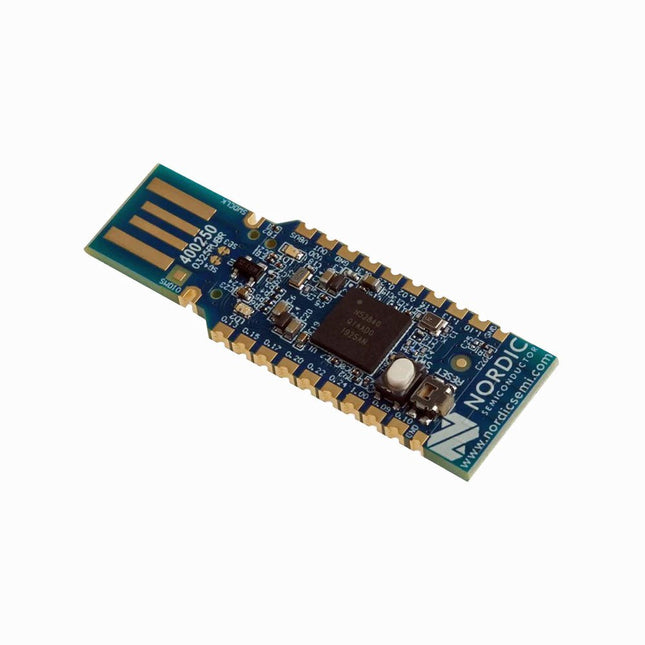
Nordic Semiconductor Nordic Semiconductor nRF52840 USB Dongle
The nRF52840 dongle is a small, low-cost USB dongle that supports Bluetooth 5.3, Bluetooth mesh, Thread, ZigBee, 802.15.4, ANT and 2.4 GHz proprietary protocols. The dongle is the perfect target hardware for use with nRF Connect for Desktop as it is low-cost but still support all the short range wireless standards used with Nordic devices. The dongle has been designed to be used as a wireless HW device together with nRF Connect for Desktop. For other use cases please do note that there is no debug support on the dongle, only support for programming the device and communicating through USB. It is supported by most of the nRF Connect for Desktop apps and will automatically be programmed if needed. In addition custom applications can be compiled and downloaded to the dongle. It has a user programmable RGB LED, a green LED, a user programmable button as well as 15 GPIO accessible from castellated solder points along the edge. Example applications are available in the nRF5 SDK under the board name PCA10059. The nRF52840 dongle is supported by nRF Connect for Desktop as well as programming through nRFUtil. Features Bluetooth 5.2 ready multiprotocol radio 2 Mbps Long Range Advertising Extensions Channel Selection Algorithm #2 (CSA #2) IEEE 802.15.4 radio support Thread ZigBee Arm Cortex-M4 with floating point support DSP instruction set ARM CryptoCell CC310 cryptographic accelerator 15 GPIO available via edge castellation USB interface direct to nRF52840 SoC Integrated 2.4 GHz PCB antenna 1 user-programmable button 1 user-programmable RGB LED 1 user-programmable LED 1.7-5.5 V operation from USB or external Downloads Datasheet Hardware Files
€ 19,95
Members € 17,96
-
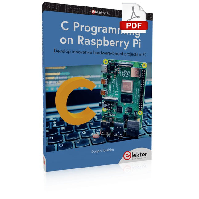
Elektor Digital C Programming on Raspberry Pi (E-book)
Develop innovative hardware-based projects in C The Raspberry Pi has traditionally been programmed using Python. Although this is a very powerful language, many programmers may not be familiar with it. C on the other hand is perhaps the most commonly used programming language and all embedded microcontrollers can be programmed using it. The C language is taught in most technical colleges and universities and almost all engineering students are familiar with using it with their projects. This book is about using the Raspberry Pi with C to develop a range of hardware-based projects. Two of the most popular C libraries, wiringPi and pigpio are used. The book starts with an introduction to C and most students and newcomers will find this chapter invaluable. Many projects are provided in the book, including using Wi-Fi and Bluetooth to establish communication with smartphones. Many sensor and hardware-based projects are included. Both wiringPi and pigpio libraries are used in all projects. Complete program listings are given with full explanations. All projects have been fully tested and work. The following hardware-based projects are provided in the book: Using sensors Using LCDs I²C and SPI buses Serial communication Multitasking External and timer interrupts Using Wi-Fi Webservers Communicating with smartphones Using Bluetooth Sending data to the cloud Program listings of all Raspberry Pi projects developed in this book are available on the Elektor website. Readers can download and use these programs in their projects. Alternatively, they can customize them to suit their applications.
€ 32,95
Members € 26,36
-
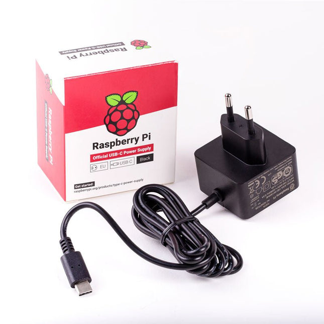
Raspberry Pi Foundation Official EU Power Supply for Raspberry Pi 4 (black)
The Raspberry Pi USB-C power supply is designed specifically to power the Raspberry Pi 4. The power supply features a USB-C cable and is available in four different models to suit different international power sockets, and in two colors. Specifications Output Output voltage +5.1 V DC Minimum load current 0 A Nominal load current 3.0 A Maximum power 15.3 W Load regulation ±5% Line regulation ±2% Ripple & noise 120 mVp-p Rise time 100 ms maximum to regulation limits for DC outputs Turn-on delay 3000 ms maximum at nominal input AC voltage and full load Protection Short circuit protectionOvercurrent protectionOver temperature protection Efficiency 81% minimum (output current from 100%, 75%, 50%, 25%)72% minimum at 10% load Output cable 1.5 m 18AWG Output connector USB-C Input Voltage range 100-240 V AC (rated)96-264 V AC (operating) Frequency 50/60 Hz ±3 Hz Current 0.5 A maximum Power consumption (no load) 0.075 W maximum Inrush current No damage shall occur, and the input fuse shall not blow Operating ambient temperature 0-40°C
€ 9,95
Members identical
-
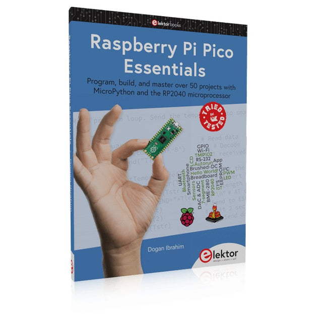
Elektor Publishing Raspberry Pi Pico Essentials
Program, build, and master over 50 projects with MicroPython and the RP2040 microprocessor The Raspberry Pi Pico is a high-performance microcontroller module designed especially for physical computing. Microcontrollers differ from single-board computers, like the Raspberry Pi 4, in not having an operating system. The Raspberry Pi Pico can be programmed to run a single task very efficiently within real-time control and monitoring applications requiring speed. The ‘Pico’ as we call it, is based on the fast, efficient, and low-cost dual-core ARM Cortex-M0+ RP2040 microcontroller chip running at up to 133 MHz and sporting 264 KB of SRAM, and 2 MB of Flash memory. Besides its large memory, the Pico has even more attractive features including a vast number of GPIO pins, and popular interface modules like ADC, SPI, I²C, UART, and PWM. To cap it all, the chip offers fast and accurate timing modules, a hardware debug interface, and an internal temperature sensor. The Raspberry Pi Pico is easily programmed using popular high-level languages such as MicroPython and or C/C++. This book is an introduction to using the Raspberry Pi Pico microcontroller in conjunction with the MicroPython programming language. The Thonny development environment (IDE) is used in all the projects described. There are over 50 working and tested projects in the book, covering the following topics: Installing the MicroPython on Raspberry Pi Pico using a Raspberry Pi or a PC Timer interrupts and external interrupts Analogue-to-digital converter (ADC) projects Using the internal temperature sensor and external temperature sensor chips Datalogging projects PWM, UART, I²C, and SPI projects Using Wi-Fi and apps to communicate with smartphones Using Bluetooth and apps to communicate with smartphones Digital-to-analogue converter (DAC) projects All projects given in the book have been fully tested and are working. Only basic programming and electronics experience is required to follow the projects. Brief descriptions, block diagrams, detailed circuit diagrams, and full MicroPython program listings are given for all projects described. Readers can find the program listings on the Elektor web page created to support the book.
€ 39,95
Members € 35,96
-
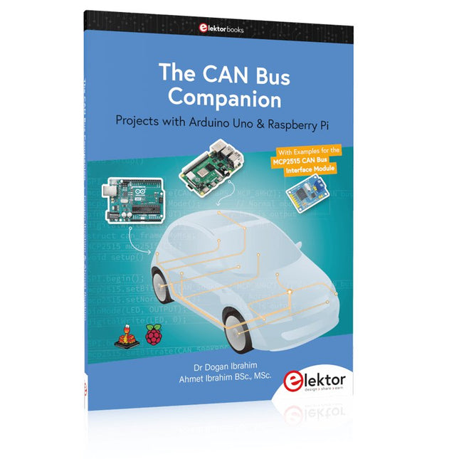
Elektor Publishing The CAN Bus Companion
This book details the use of the Arduino Uno and the Raspberry Pi 4 in practical CAN bus based projects. Using either the Arduino Uno or the Raspberry Pi with off-the-shelf CAN bus interface modules considerably ease developing, debugging, and testing CAN bus based projects. This book is written for students, practicing engineers, enthusiasts, and for everyone else wanting to learn more about the CAN bus and its applications. The book assumes that the reader has some knowledge of basic electronics. Knowledge of the C and Python programming languages and programming the Arduino Uno using its IDE and Raspberry Pi will be useful, especially if the reader intends to develop microcontroller-based projects using the CAN bus. The book should be a useful source of reference material for anyone interested in finding answers to questions such as: What bus systems are available for the automotive industry? What are the principles of the CAN bus? How can I create a physical CAN bus? What types of frames (or data packets) are available in a CAN bus system? How can errors be detected in a CAN bus system and how dependable is a CAN bus system? What types of CAN bus controllers exist? How do I use the MCP2515 CAN bus controller? How do I create 2-node Arduino Uno-based CAN bus projects? How do I create 3-node Arduino Uno-based CAN bus projects? How do I set the acceptance masks and acceptance filters? How do I analyze data on the CAN bus? How do I create 2-node Raspberry Pi-based CAN bus projects? How do I create 3-node Raspberry Pi-based CAN bus projects?
€ 34,95
Members € 31,46
-
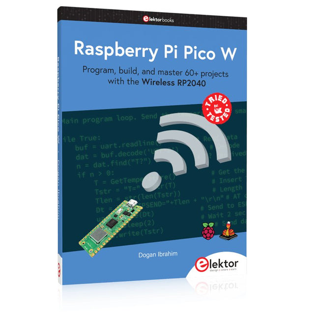
Elektor Publishing Raspberry Pi Pico W (Book)
Program, build, and master 60+ projects with the Wireless RP2040 The Raspberry Pi Pico and Pico W are based on the fast, efficient, and low-cost dual-core ARM Cortex M0+ RP2040 microcontroller chip running at up to 133 MHz and sporting 264 KB of SRAM and 2 MB of Flash memory. Besides spacious memory, the Pico and Pico W offer many GPIO pins, and popular peripheral interface modules like ADC, SPI, I²C, UART, PWM, timing modules, a hardware debug interface, and an internal temperature sensor. The Raspberry Pi Pico W additionally includes an on-board Infineon CYW43439 Bluetooth and Wi-Fi chipset. At the time of writing this book, the Bluetooth firmware was not yet available. Wi-Fi is however fully supported at 2.4 GHz using the 802.11b/g/n protocols. This book is an introduction to using the Raspberry Pi Pico W in conjunction with the MicroPython programming language. The Thonny development environment (IDE) is used in all of the 60+ working and tested projects covering the following topics: Installing the MicroPython on Raspberry Pi Pico using a Raspberry Pi or a PC Timer interrupts and external interrupts Analogue-to-digital converter (ADC) projects Using the internal temperature sensor and external sensor chips Using the internal temperature sensor and external temperature sensor chips Datalogging projects PWM, UART, I²C, and SPI projects Using Bluetooth, WiFi, and apps to communicate with smartphones Digital-to-analogue converter (DAC) projects All projects are tried & tested. They can be implemented on both the Raspberry Pi Pico and Raspberry Pi Pico W, although the Wi-Fi-based subjects will run on the Pico W only. Basic programming and electronics experience are required to follow the projects. Brief descriptions, block diagrams, detailed circuit diagrams, and full MicroPython program listings are given for all projects.
€ 44,95
Members identical
-
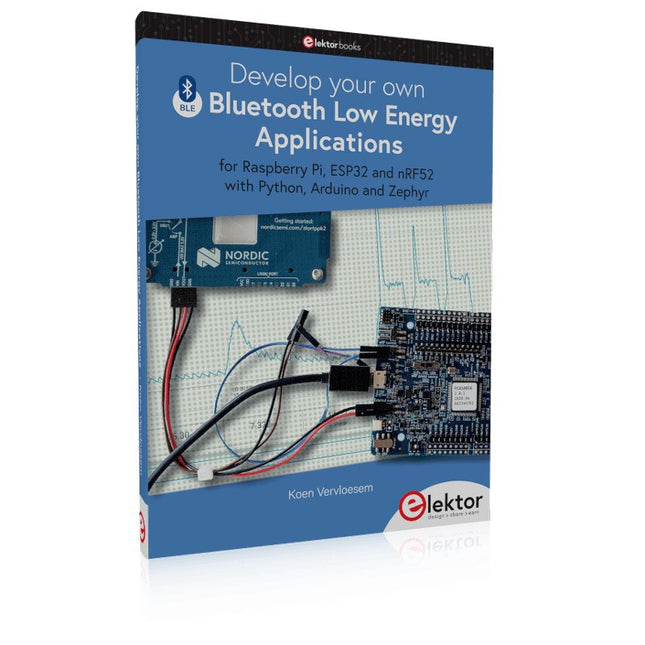
Elektor Publishing Develop your own Bluetooth Low Energy Applications
For Raspberry Pi, ESP32 and nRF52 with Python, Arduino and Zephyr Bluetooth Low Energy (BLE) radio chips are ubiquitous from Raspberry Pi to light bulbs. BLE is an elaborate technology with a comprehensive specification, but the basics are quite accessible. A progressive and systematic approach will lead you far in mastering this wireless communication technique, which is essential for working in low power scenarios. In this book, you’ll learn how to: Discover BLE devices in the neighborhood by listening to their advertisements. Create your own BLE devices advertising data. Connect to BLE devices such as heart rate monitors and proximity reporters. Create secure connections to BLE devices with encryption and authentication. Understand BLE service and profile specifications and implement them. Reverse engineer a BLE device with a proprietary implementation and control it with your own software. Make your BLE devices use as little power as possible. This book shows you the ropes of BLE programming with Python and the Bleak library on a Raspberry Pi or PC, with C++ and NimBLE-Arduino on Espressif’s ESP32 development boards, and with C on one of the development boards supported by the Zephyr real-time operating system, such as Nordic Semiconductor's nRF52 boards. Starting with a very little amount of theory, you’ll develop code right from the beginning. After you’ve completed this book, you’ll know enough to create your own BLE applications.
€ 39,95
Members € 35,96
-
Raspberry Pi Foundation microSD Card pre-installed with Raspberry Pi OS (32 GB)
With this microSD (32 GB) with pre-installed Raspberry Pi OS you can start using your Raspberry Pi right away. Just plug it in and get started!
€ 10,95
Members identical
-
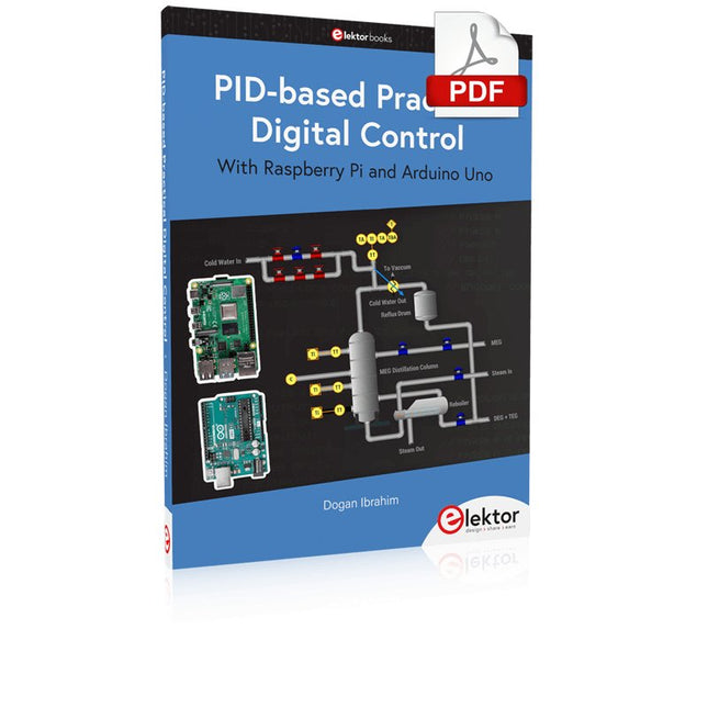
Elektor Digital PID-based Practical Digital Control with Raspberry Pi and Arduino Uno (E-book)
The Arduino Uno is an open-source microcontroller development system encompassing hardware, an Integrated Development Environment (IDE), and a vast number of libraries. It is supported by an enormous community of programmers, electronic engineers, enthusiasts, and academics. The libraries in particular really smooth Arduino programming and reduce programming time. What’s more, the libraries greatly facilitate testing your programs since most come fully tested and working. The Raspberry Pi 4 can be used in many applications such as audio and video media devices. It also works in industrial controllers, robotics, games, and in many domestic and commercial applications. The Raspberry Pi 4 also offers Wi-Fi and Bluetooth capability which makes it great for remote and Internet-based control and monitoring applications. This book is about using both the Raspberry Pi 4 and the Arduino Uno in PID-based automatic control applications. The book starts with basic theory of the control systems and feedback control. Working and tested projects are given for controlling real-life systems using PID controllers. The open-loop step time response, tuning the PID parameters, and the closed-loop time response of the developed systems are discussed together with the block diagrams, circuit diagrams, PID controller algorithms, and the full program listings for both the Raspberry Pi and the Arduino Uno. The projects given in the book aim to teach the theory and applications of PID controllers and can be modified easily as desired for other applications. The projects given for the Raspberry Pi 4 should work with all other models of Raspberry Pi family. The book covers the following topics: Open-loop and closed-loop control systems Analog and digital sensors Transfer functions and continuous-time systems First-order and second-order system time responses Discrete-time digital systems Continuous-time PID controllers Discrete-time PID controllers ON-OFF temperature control with Raspberry Pi and Arduino Uno PID-based temperature control with Raspberry Pi and Arduino Uno PID-based DC motor control with Raspberry Pi and Arduino Uno PID-based water level control with Raspberry Pi and Arduino Uno PID-based LED-LDR brightness control with Raspberry Pi and Arduino Uno
€ 32,95
Members € 26,36
-
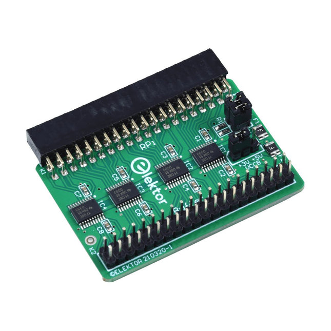
Elektor Labs Elektor Raspberry Pi Buffer Board
When you experiment with the Raspberry Pi on a regular basis and you connect a variety of external hardware to the GPIO port via the header you may well have caused some damage in the past. The Elektor Raspberry Pi Buffer Board is there to prevent this! The board is compatible with Raspberry Pi Zero, Zero 2 (W), 3, 4, 5, 400 and 500. All 26 GPIOs are buffered with bi-directional voltage translators to protect the Raspberry Pi when experimenting with new circuits. The PCB is intended to be inserted in the back of Raspberry Pi 400/500. The connector to connect to the Raspberry Pi is a right angled 40-way receptacle (2x20). The PCB is only a fraction wider. A 40-way flat cable with appropriate 2x20 headers can be connected to the buffer output header to experiment for instance with a circuit on a breadboard or PCB. The circuit uses 4x TXS0108E ICs by Texas Instruments. The PCB can also be put upright on a Raspberry Pi. Downloads Schematics Layout
€ 34,95€ 29,95
Members identical
-
Elektor Digital Control Your Home with Raspberry Pi (E-book)
Secure, Modular, Open-Source and Self-Sufficient Ever since the Raspberry Pi was introduced, it has been used by enthusiasts to automate their homes. The Raspberry Pi is a powerful computer in a small package, with lots of interfacing options to control various devices. This book shows you how you can automate your home with a Raspberry Pi. You’ll learn how to use various wireless protocols for home automation, such as Bluetooth, 433.92 MHz radio waves, Z-Wave, and Zigbee. Soon you’ll automate your home with Python, Node-RED, and Home Assistant, and you’ll even be able to speak to your home automation system. All this is done securely, with a modular system, completely open-source, without relying on third-party services. You’re in control of your home, and no one else. At the end of this book, you can install and configure your Raspberry Pi as a highly flexible home automation gateway for protocols of your choice, and link various services with MQTT to make it your own system. This DIY (do it yourself) approach is a bit more laborious than just installing an off-the-shelf home automation system, but in the process, you can learn a lot, and in the end, you know exactly what’s running your house and how to tweak it. This is why you were interested in the Raspberry Pi in the first place, right? Turn your Raspberry Pi into a reliable gateway for various home automation protocols. Make your home automation setup reproducible with Docker Compose. Secure all your network communication with TLS. Create a video surveillance system for your home. Automate your home with Python, Node-RED, Home Assistant and AppDaemon. Securely access your home automation dashboard from remote locations. Use fully offline voice commands in your own language. Download the software and view the errata for the book on GitHub.
€ 34,95
Members € 27,96
-

Raspberry Pi Foundation Official HDMI Cable for Raspberry Pi (black, 1 m)
The official Raspberry Pi micro HDMI to HDMI (A/M) cable (black, 1 m) designed for the Raspberry Pi 4 and 5. 19-pin HDMI Type D(M) to 19-pin HDMI Type A(M) 1 m cable (black) Nickel-plated plugs 4Kp60 compliant RoHS compliant 3 Mohm 300 VDC insulation, withstands 300 VDC for 0.1s
€ 6,95
Members identical
-
Raspberry Pi Foundation Official EU Power Supply for Raspberry Pi 4 (white)
The Raspberry Pi USB-C power supply is designed specifically to power the Raspberry Pi 4. The power supply features a USB-C cable and is available in four different models to suit different international power sockets, and in two colors. Specifications Output Output voltage +5.1 V DC Minimum load current 0 A Nominal load current 3.0 A Maximum power 15.3 W Load regulation ±5% Line regulation ±2% Ripple & noise 120 mVp-p Rise time 100 ms maximum to regulation limits for DC outputs Turn-on delay 3000 ms maximum at nominal input AC voltage and full load Protection Short circuit protectionOvercurrent protectionOver temperature protection Efficiency 81% minimum (output current from 100%, 75%, 50%, 25%)72% minimum at 10% load Output cable 1.5 m 18AWG Output connector USB-C Input Voltage range 100-240 V AC (rated)96-264 V AC (operating) Frequency 50/60 Hz ±3 Hz Current 0.5 A maximum Power consumption (no load) 0.075 W maximum Inrush current No damage shall occur, and the input fuse shall not blow Operating ambient temperature 0-40°C
€ 9,95
Members identical
-
Elektor Classics The Complete Linear Audio Library (USB Stick)
Jan Didden created Linear Audio in 2010 and published 14 Volumes between 2010 and 2017. Each 200-page Volume contains on average 10 articles by expert authors in the field of audio, acoustics, and instrumentation. Whether you are interested in tube amplifiers, solid-state equipment, loudspeaker design, capacitor and resistor distortion or distortion measurement, you are certain to find helpful advice and interesting discussions. From beginner to advanced level, for the audio professional or the serious hobbyist, this ExpertCollection will advance your understanding and offer new perspectives on common issues. Bonus material included with this collection is a 5-part YouTube series on negative feedback as applied to audio by renowned author Jan Didden, and nine additional landmark audio articles and presentations. If you are seriously interested in audio, acoustics, and instrumentation, you can’t afford to miss this! The published material is indexed and fully searchable and will provide an almost limitless resource for many years to come. You can read about Linear Audio’s authors, and the Table of Contents of each Volume, at linearaudio.net.
€ 149,95€ 74,95
Members identical
-

Elektor Publishing Practical Audio DSP Projects with the ESP32
Easy and Affordable Digital Signal Processing The aim of this book is to teach the basic principles of Digital Signal Processing (DSP) and to introduce it from a practical point of view using the bare minimum of mathematics. Only the basic level of discrete-time systems theory is given, sufficient to implement DSP applications in real time. The practical implementations are described in real time using the highly popular ESP32 DevKitC microcontroller development board. With the low cost and extremely popular ESP32 microcontroller, you should be able to design elementary DSP projects with sampling frequencies within the audio range. All programming is done using the popular Arduino IDE in conjunction with the C language compiler. After laying a solid foundation of DSP theory and pertinent discussions on the main DSP software tools on the market, the book presents the following audio-based sound and DSP projects: Using an I²S-based digital microphone to capture audio sound Using an I²S-based class-D audio amplifier and speaker Playing MP3 music stored on an SD card through an I²S-based amplifier and speaker Playing MP3 music files stored in ESP32 flash memory through an I²S-based amplifier and speaker Mono and stereo Internet radio with I²S-based amplifiers and speakers Text-to-speech output with an I²S-based amplifier and speaker Using the volume control in I²S-based amplifier and speaker systems A speaking event counter with an I²S-based amplifier and speaker An adjustable sinewave generator with I²S-based amplifier and speaker Using the Pmod I²S2 24-bit fast ADC/DAC module Digital low-pass and band-pass real-time FIR filter design with external and internal A/D and D/A conversion Digital low-pass and band-pass real-time IIR filter design with external and internal A/D and D/A conversion Fast Fourier Transforms (FFT)
€ 39,95
Members € 35,96
-
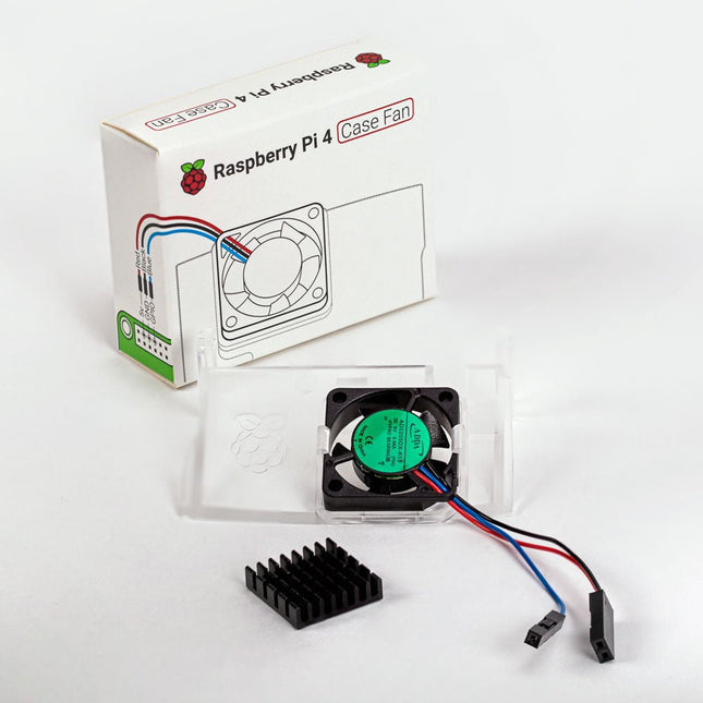
Raspberry Pi Foundation Raspberry Pi 4 Case Fan
Designed for overclockers and other power users, this fan keeps your Raspberry Pi 4 at a comfortable operating temperature even under heavy load. The temperature-controlled fan delivers up to 1.4 CFM of airflow over the processor, memory, and power management IC. The bundled heatsink (18 x 8 x 10 mm) with self-adhesive pad improves heat transfer from the processor. The Raspberry Pi 4 Case Fan works with Raspberry Pi 4 and the official Raspberry Pi 4 case.
€ 6,95€ 4,95
Members identical
-
Elektor Digital Elektor Arduino Guest Edition 2022 (PDF) EN
Elektor GREEN and GOLD members can download their digital edition here. Not a member yet? Click here. Arduino Portenta Machine Control and Arduino Portenta H7A CAN-to-MQTT Gateway Demo Project Unboxing the Elektor LCR Meter with David Cuartielles MicroPython Enters the World of Arduino Connected Projects, SimplifiedDive Into the Arduino Cloud Introduction to TinyMLBig Is Not Always Better Arduino K-Way Writing Arduino Sketches Just Got Better Get to Know Arduino Getting Started with the Portenta X8Manage Software Securely with Containers Build, Deploy, and Maintain Scalable, Secure ApplicationsWith Arduino Portenta X8 Featuring NXP’s i.MX 8M Mini Applications Processor and EdgeLock SE050 Secure Element How I Automated My HomeArduino CEO Fabio Violante Shares Solutions Altair 8800 SimulatorHardware Simulation of a Vintage Computer MS-DOS on the Portenta H7Run Old-School Software on Contemporary Hardware Grow It YourselfA Digitally Controlled, Single-Box Solution for Indoor Farming Save the Planet With Home Automation?MQTT on the Arduino Nano RP2040 Connect Go Professional with Arduino Pro Smart Ovens Take a Leap Into the Future Tagvance Builds Safer Construction Sites with Arduino Santagostino Breathes Easywith Remote Monitoring that Leverages AI for Predictive Maintenance Security Flies High with RIoT Secure’s MKR-Based Solution Open-Source Brings a New Generation of Water Management to the World SensoDetect Deforestation with Sound Analysis The Mozzi Arduino Library for Sound SynthesisInsights from Tim Barrass The New Portenta X8 (with Linux!) and Max Carrier Redefine What’s Possible How Using Arduino Helps Students Build Future Skills Must-Haves for Your Electronics Workspace The Importance of Robotics in Education Dependable IoT Based Upon LoRa Unboxing the Portenta Machine Control 8-Bit Gaming with Arduboy Reducing Water Usage at Horseback Riding TracksAn IoT to Constantly Monitor Soil Humidity and Temperature Levels The Panettone ProjectA sourdough starter management and maintenance system Supporting Arduino Resellers Space Invaders with Arduino Art with ArduinoInspiring Insights from Artists and Designers Arduino Product Catalogue The Future of Arduino
€ 7,50
-
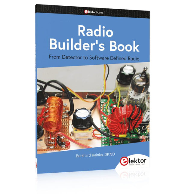
Elektor Publishing Radio Builder's Book
From Detector to Software Defined Radio Radio frequency (RF) technology is one of the areas which still allows putting your own ideas into practice. Countless circuit variants with special objectives allow space for meaningful experiments and projects. Many things simply aren’t available off the shelf. Crystal detector radios without their own power source, simple tube receivers with a touch of nostalgia, the first reception attempts at Software Defined Radio, special receivers for amateur radio, all this can be realized with little effort and as a perfect introduction to RF electronics. For a long time, radio construction was the first step into electronics. Meanwhile, there are other ways, especially via computers, microcontrollers, and digital technology. However, the analog roots of electronics are often neglected. Elementary radio technology and easy-to-do experiments are particularly well suited as a learning field for electronics because you can start with the simplest basics here. But the connection to modern digital technology is also obvious, for example, when it comes to modern tuning methods such as PLL and DDS or modern DSP radios. This book aims to give an overview and present a collection of simple RF projects. The author would like to support you to develop your own ideas, to design your own receivers and to test them.
€ 39,95
Members € 35,96


