Nowadays, more and smarter phones and laptops adopt USB-C ports for its powerful function that can transmit power, data, and video information. USB-C solution can also make the device much thinner compared to the Thunderbolt 3 or HDMI-compatible port. That’s why we the CrowVi portable USB-C monitor was created. The super thin CrowVi 13.3' monitor has 2 USB-C ports, one is for power delivery, and the other is for data transmission of video and touch screen commands. The screen also can be connected through the mini HDMI-compatible port. The resolution of CrowVi is 1920x1080, which will provide a better experience for gaming and watching movies. Features CrowVi shell is made of aluminum alloy, its thickness is as thin as 5 mm, and the screen border is as narrow as 6 mm. The whole monitor looks exquisite and elegant. CrowVi can not only act as the dual monitor for smartphones, and laptops but also as the single monitor for gaming devices and some computer mainframes like Mac mini, Raspberry Pi, etc. CrowVi brings you a much larger view compared to the phone. It enables better experiences for gaming and watching movies. Specifications Screen 13.3' TFT IPS LCD Screen Size 294.5 x 164 mm Thickness 5-10 mm Resolution 1920 x 1080 Brightness 300 nits Refresh Rate 60 Hz Color Gamut 16.7M, NTSC 72%, sRGB up to 100% Contrast 800:1 Backlight LED Viewing Angle 178° Aspect Ratio 16:9 Speaker Dual speakers 8 Ω, 2 W Shell Aluminum alloy Input Mini-HD, Type-C, PD Output 3.5 mm headphone jack Power PD 5-20 V or USB-C 3.0 Operating Temperature 0-50°C Dimensions 313 x 198 x 10 mm Weight (Smart Case) 350 g Weight (Monitor) 700 g Included 13.3-inch Touch screen monitor Smart case USB-C to USB-C cable (1 m) USB-A to USB-C power cable (1 m) HDMI to mini-HDMI cable (1 m) Power adapter (5 V/2 A) HDMI to mini-HDMI adapter Dust cloth User manual Downloads User manual
This display features an IPS resolution of 480x480 with capacitive touch and a frame rate of up to 75 FPS. It is very bright and has 65,000 colors. The mechanical rotary encoder supports clockwise/counterclockwise rotation and also supports the entire pressing process, which can usually be used to confirm the process. The display module is based on ESP32-S3 with WiFi & Bluetooth 5.0 to easily connect to the Internet for IoT projects. It can be powered and programmed directly via the USB port. It also has two expansion ports, I²C and UART. Specifications Controller ESP32-S3 WROOM-1-N16R8 (16 MB Flash, 8 MB PSRAM, PCB antenna) Wireless WiFi & Bluetooth 5.0 Resolution 480x480 LCD 2.1' IPS LCD, 65K color LCD driver ST7701S Frame rate >70 FPS LCD interface RGB 565 Touch panel 5-points capacitive touch Touch panel driver CST8266 USB USB-C native Interfaces 1x I²C, 1x UART (1.25 mm, 4-pin connector) Arduino support Yes Downloads Wiki Usage with Squareline/LVGL GitHub Datasheet_ESP32-S3-WROOM-1
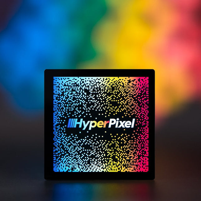
HyperPixel 4.0 Square has all the great features of our standard HyperPixel 4.0 – a crisp, brilliant IPS display with touchscreen, and high-speed DPI interface – it's just more square!
This square version of HyperPixel 4.0 is great for custom interfaces and control panels, and works really well for Pico-8 games. Everything is pre-soldered and ready to go, just pop it onto your RPi, run our installer, and away you go!
Features
High-speed DPI interface
4.0" IPS (wide viewing angle, 160°) display (72x72 mm)
720x720 pixels (~254 PPI)
18-bit colour (262,144 colors)
60 FPS frame rate
Optional capacitive touchscreen
40-pin female header included to boost height for Raspberry Pi B+, 2, 3, 3B+ and 4
Standoffs included to securely attach to your RPi
Compatible with all 40-pin header Raspberry Pi models
One-line installer
HyperPixel 4.0 Square uses a high-speed DPI interface, allowing it to shift 5x more pixel data than the usual SPI interface that these small RPi displays normally use. It has a 60 FPS frame rate and a resolution of approximately 254 pixels per inch (720x720px) on its 4.0' display. The display can show 18-bits of colour (262,144 colors).
This Touch version has a capacitive touch display that's more sensitive and responsive to touch than a resistive touch display, and it's capable of multi-touch!
Please note: when installing HyperPixel 4.0 Square onto your RPi make sure not to press down on the screen surface! Hold the board by its edges and wiggle it to mate with the extended header (or GPIO header). Also take care not to pull on the edges of the glass display when removing your HyperPixel.
It'll work with any 40-pin version of the RPi, including RPi Zero and RPi Zero W. If you're using it with a larger RPi then use the extra 40-pin header that's included to boost it up to the required height. If you're using a Zero or Zero W then just pop it straight onto the GPIO.
The included standoff kit allows you to mount your HyperPixel 4.0 Square safely and securely to your RPi. Just screw them into the posts on the underside of the HyperPixel 4.0 Square PCB and then secure with screws through the mounting holes on your RPi.
Downloads
GitHub
Example projects with Node-RED, MQTT, WinCC SCADA, Blynk, and ThingSpeak
This comprehensive guide unlocks the power of Modbus TCP/IP communication with Arduino. From the basics of the Modbus protocol right up to full implementation in Arduino projects, the book walks you through the complete process with lucid explanations and practical examples.
Learn how to set up Modbus TCP/IP communication with Arduino for seamless data exchange between devices over a network. Explore different Modbus functions and master reading and writing registers to control your devices remotely. Create Modbus client and server applications to integrate into your Arduino projects, boosting their connectivity and automation level.
With detailed code snippets and illustrations, this guide is perfect for beginners and experienced Arduino enthusiasts alike. Whether you‘re a hobbyist looking to expand your skills or a professional seeking to implement Modbus TCP/IP communication in your projects, this book provides all the knowledge you need to harness the full potential of Modbus with Arduino.
Projects covered in the book:
TCP/IP communication between two Arduino Uno boards
Modbus TCP/IP communication within the Node-RED environment
Combining Arduino, Node-RED, and Blynk IoT cloud
Interfacing Modbus TCP/IP with WinCC SCADA to control sensors
Using MQTT protocol with Ethernet/ESP8266
Connecting to ThingSpeak IoT cloud using Ethernet/ESP8266
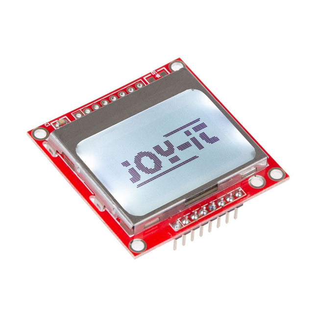
This display correspond to the Nokia 5110 norm which makes it perfectly to display data or graphs of measured values on a microcontroller or a single-board computer. Additionally, the display is compatible to all Raspberry Pi, Arduino, CubieBoard, Banana Pi and microcontroller without additional effort. Specifications Chipset Philips PCD8544 Interface SPI Resolution 84 x 48 Pixels Power supply 2.7-3.3 V Special features Backlight Compatible to Raspberry Pi, Arduino, CubieBoard, Banana Pi and microcontroller Dimensions 45 x 45 x 14 mm Weight 14 g
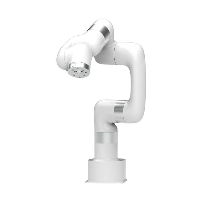
This multi-axis robot perfectly balances power and size.
Features
6 Axis
Payload: 3.5 kg
Reach: 700 mm
Repeatability: 0.1 mm
Max Speed 1000 mm/s
Applications
Machine Tending
Bin Picking
Mobile platform
Lab Automation
Robotic Research
Durable Collaborative robots for your automation
Industrial-grade harmonic drive and servomotors guarantee 24/7 working without stop.
Crafted from Carbon fiber, 15 kg weight makes it possible for easier deployment.
Flexible deployment with safe feature
Hand teaching, lightweight, space-saving and easy to re-deploy to multiple applications without changing your production layout. Perfectly for recurrent tasks.
Collision detection is available for all of our cobots. Your safety is always the top priority.
Graphical interface for beginner-friendly programming
Compatible with various of operation systems, including macOS and Windows.
Web-based technology compatible with all major browsers.
Drag and drop to create your code in minutes.
Powerful and open source SDK at your fingertips
Fully functional open-source Python/C++ SDK provides more flexible programming.
ROS/ROS2 packages are ready-to-go.
Example codes help you to deploy the robotic arm smoothly.
Specifications
UFactory 850
xArm 5
xArm 6
xArm 7
Payload
5 kg
3 kg
5 kg
3.5 kg
Reach
850 mm
700 mm
700 mm
700 mm
Degrees of freedom
6
5
6
7
Repeatability
±0.02 mm
±0.1 mm
±0.1 mm
±0.1 mm
Maximum Speed
1 m/s
1 m/s
1 m/s
1 m/s
Weight (robot arm only)
20 kg
11.2 kg
12.2 kg
13.7 kg
Maximum Speed
180°/s
180°/s
180°/s
180°/s
Joint 1
±360°
±360°
±360°
±360°
Joint 2
-132°~132°
-118°~120°
-118°~120°
-118°~120°
Joint 3
-242°~3.5°
-225°~11°
-225°~11°
±360°
Joint 4
±360°
-97°~180°
±360°
-11°~225°
Joint 5
-124°~124°
±360°
-97°~180°
±360°
Joint 6
±360°
±360°
-97°~180°
Joint 7
±360°
Hardware
Ambient Temperature Range
0-50°C
Power Consumption
Min 8.4 W, Typical 200 W, max 400 W
Input Power Supply
24 V DC, 16.5 A
Footprint
Ø 126 mm
Materials
Aluminum, Carbon Fiber
Base Connector Type
M5x5
ISO Class Cleanroom
5
Robot Mounting
Any
End Effector Communication Protocol
Modbus RTU(rs485)
End Effector I/O
2x DI/2x DO/2x AI/1x RS485
Communication Mode
Ethernet
Included
1x xArm 7 robotic arm
1x AC control box
1x Robotic arm power cable
1x Robotic arm end effector adapter cable
1x Robotic arm signal cable
1x Control box power cable
1x Network cable
1x Mounting tool
1x Quick start guide
Example projects with Node-RED, MQTT, WinCC SCADA, Blynk, and ThingSpeak
This comprehensive guide unlocks the power of Modbus TCP/IP communication with Arduino. From the basics of the Modbus protocol right up to full implementation in Arduino projects, the book walks you through the complete process with lucid explanations and practical examples.
Learn how to set up Modbus TCP/IP communication with Arduino for seamless data exchange between devices over a network. Explore different Modbus functions and master reading and writing registers to control your devices remotely. Create Modbus client and server applications to integrate into your Arduino projects, boosting their connectivity and automation level.
With detailed code snippets and illustrations, this guide is perfect for beginners and experienced Arduino enthusiasts alike. Whether you‘re a hobbyist looking to expand your skills or a professional seeking to implement Modbus TCP/IP communication in your projects, this book provides all the knowledge you need to harness the full potential of Modbus with Arduino.
Projects covered in the book:
TCP/IP communication between two Arduino Uno boards
Modbus TCP/IP communication within the Node-RED environment
Combining Arduino, Node-RED, and Blynk IoT cloud
Interfacing Modbus TCP/IP with WinCC SCADA to control sensors
Using MQTT protocol with Ethernet/ESP8266
Connecting to ThingSpeak IoT cloud using Ethernet/ESP8266
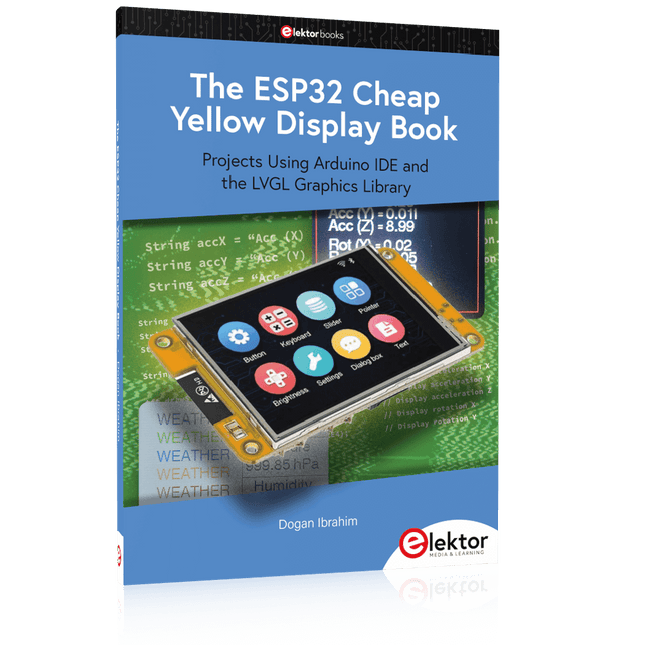
Projects Using Arduino IDE and the LVGL Graphics Library
The ESP32 is probably one of the most popular microcontrollers used by many people, including students, hobbyists, and professional engineers. Its low cost, coupled with rich features makes it a popular device to use in many projects. Recently, a board called the ESP32 Cheap Yellow Display (CYD for short) is available from its manufacturers. The board includes a standard ESP32 microcontroller together with a 320x240 pixel TFT display. Additionally, the board provides several connectors for interfaces such as GPIO, serial port (TX/RX), power and Ground. The inclusion of a TFT display is a real advantage as it enables users to design complex graphics-based projects without resorting to an external LCD or graphics displays.
The book describes the basic hardware of the ESP32 CYD board and provides details of its on-board connectors. Many basic, simple, and intermediate-level projects are given in the book based on the ESP32 CYD, using the highly popular Arduino IDE 2.0 integrated development environment. The use of both the basic graphics functions and the use of the popular LVGL graphics library are discussed in the book and projects are given that use both types of approaches.
All the projects given in the book have been tested and are working. The block diagram, circuit diagram, and the complete program listings and program descriptions of all the projects are given with explanations. Readers can use the LVGL graphics library to design highly popular eye-catching full-color graphics projects using widgets such as buttons, labels, calendars, keypads, keyboards, message boxes, spinboxes, sliders, charts, tables, menus, bars, switches, drop-down lists, animations, and many more widgets.
This DIY Color Display Kit is a fun and educational project for makers of all ages. It is a great way to learn about electronics, programming, and improve your soldering skills.
Microcontroller
As this kit ships with the ePulse Feather ESP32 development board, the kit thereby inherits all the great features of said devkit.
Display
The large 3.5" 320x480 color display also sports a high-precision capacitive touch interface. Contrary to resistive touch interfaces that often work best when using a stylus this auto-calibrated module offers a smartphone-like user experience.
Connector PCB
The connectors for the display are already pre-assembled on the connector PCB, as those require a more experienced hand at the soldering iron. Hence, for the inexperienced solderer this offers the best of both worlds. Also, you may choose to not add the on-off switch or the Grove connector; both are optional.
The connector PCB offers extendability in two ways: the broken out pins of the microcontroller and the connector for the Grove system.
Specifications
Microcontroller
ESP32
Module
ePulse Feather
Display Resolution
320 x 480
Display Driver
ILI9488
Touch Display
Capacitive
Included
1x ePulse Feather, low-power ESP32 development board
1x 3.5" 320x480 Color Display (ILI9488, TFT) with capacitive touch Interface (FT6236) Color Kit Grande Connector Board
1x Custom connector PCB to connect the ESP32 and the display Header Pins
1x Set of special pin headers (to be soldered to connector PCB Color Kit Power Switch)
1x On-off switch (to be optionally soldered to connector PCB SMD Grove Connector)
1x Grove connector (to be optionally soldered to connector PCB Color Kit Grande Foam Stickers)
4x Double-sided foam adhesive to secured display to PCB
Downloads
Schematics
Documentation
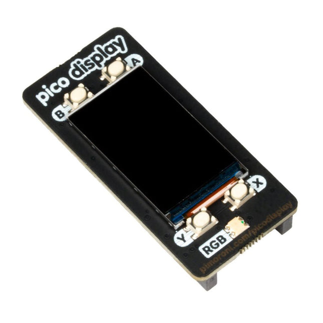
Pico Display lets you turn a Pico into a compact user interface device for a bigger project, capable of giving instructions, displaying readouts and even incorporating elaborate nested menus. If you'd rather use your Pico as a standalone device you could make a little rotating slideshow of images, display beautiful graphs from sensor data or build your own Tamagotchi or matchbox sized text adventure game.Features
1.14” 240x135 pixel IPS LCD screen
4 x tactile buttons
RGB LED
Pre-soldered female headers for attaching to Pico
Compatible with Raspberry Pi Pico.
Fully assembled
No soldering required (as long as your Pico has header pins attached).
Dimensions: approx 53 x 25 x 9 mm (L x W x H)
Screen usable area: approx 25 x 15 mm (L x W)
C/C++ and MicroPython libraries
Projects Using Arduino IDE and the LVGL Graphics Library
The ESP32 is probably one of the most popular microcontrollers used by many people, including students, hobbyists, and professional engineers. Its low cost, coupled with rich features makes it a popular device to use in many projects. Recently, a board called the ESP32 Cheap Yellow Display (CYD for short) is available from its manufacturers. The board includes a standard ESP32 microcontroller together with a 320x240 pixel TFT display. Additionally, the board provides several connectors for interfaces such as GPIO, serial port (TX/RX), power and Ground. The inclusion of a TFT display is a real advantage as it enables users to design complex graphics-based projects without resorting to an external LCD or graphics displays.
The book describes the basic hardware of the ESP32 CYD board and provides details of its on-board connectors. Many basic, simple, and intermediate-level projects are given in the book based on the ESP32 CYD, using the highly popular Arduino IDE 2.0 integrated development environment. The use of both the basic graphics functions and the use of the popular LVGL graphics library are discussed in the book and projects are given that use both types of approaches.
All the projects given in the book have been tested and are working. The block diagram, circuit diagram, and the complete program listings and program descriptions of all the projects are given with explanations. Readers can use the LVGL graphics library to design highly popular eye-catching full-color graphics projects using widgets such as buttons, labels, calendars, keypads, keyboards, message boxes, spinboxes, sliders, charts, tables, menus, bars, switches, drop-down lists, animations, and many more widgets.