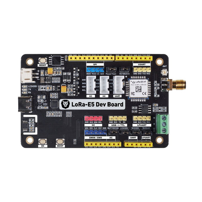
LoRa-E5 Development Kit is an easy-to-use compact development toolset for you to unlock the powerful performance of the LoRa-E5 STM32WLE5JC. It consists of a LoRa-E5 Dev Board, an antenna (EU868), a USB type C cable, and a 2-AA 3 V Battery Holder.
LoRa-E5 Dev Board embedded with LoRa-E5 STM32WLE5JC Module, which is the world-first combo of LoRa RF and MCU chip into one single tiny chip and is FCC and CE certified. It is powered by ARM Cortex-M4 core and Semtech SX126X LoRa chip, supports both LoRaWAN and LoRa protocol on the worldwide frequency and (G)FSK, BPSK, (G)MSK, and LoRa modulations.
The LoRa-E5 development board features a very long transmission range, extremely low power consumption and user-friendly interfaces.
LoRa-E5 Dev Board has a long-distance transmission range of LoRa-E5 up to 10 km in an open area. The sleep current of LoRa-E5 modules on board is as low as 2.1 uA (WOR mode). It is designed with industrial standards with a wide working temperature at -40℃ ~ 85℃, high sensitivity between -116.5 dBm ~ -136 dBm, and power output up to +20.8 dBm at 3.3 V.
LoRa-E5 Dev Board also has rich interfaces. Developed to unlock the full functionality of the LoRa-E5 module, LoRa-E5 Dev Board has led out full 28 pins of LoRa-E5 and provides with rich interfaces including Grove connectors, RS-485 terminal, male/female pin headers for you to connect sensors and modules with different connectors and data protocols, saving your time on wire soldering. You could also easily power the board by connecting the battery holder with 2-AA batteries, enabling temporary use when lacking an external power source. It is a user-friendly board for easy testing and rapid prototyping.
Specifications
Size
LoRa-E5 Dev Board: 85.6 x 54 mm
Voltage (supply)
3-5 V (Battery) / 5 V (USB-C)
Voltage (output)
EN 3V3 / 5 V
Power (output)
Up to +20.8 dBm at 3.3 V
Frequency
EU868
Protocol
LoRaWAN
Sensitivity
-116.5 dBm ~ -136 dBm
Interfaces
USB Type C / JST2.0 / 3x Grove (2x I²C/1x UART) / RS485 / SMA-K / IPEX
Modulation
LoRa, (G)FSK, (G)MSK, BPSK
Working temperature
-40℃ ~ 85℃
Current
LoRa-E5 module sleep current as low as 2.1 uA (WOR mode)
Included
1x LoRa-E5 Dev Board
1x Antenna (EU868)
1x USB Type C Cable (20 cm)
1x 2-AA 3 V Battery Holder
This is a high-performance cooling solution designed to effectively dissipate heat and ensure optimal operating temperatures for the Raspberry Pi. It is an essential accessory for users who want to enhance the performance and longevity of their Raspberry Pi device.
The compact design of the Water cooling kit for Raspberry Pi 5 allows it to be seamlessly installed on the top and bottom of the Raspberry Pi 5, ensuring efficient heat transfer and perfectly protecting the bottom of the Raspberry Pi. Its simple installation process eliminates the need for complex wiring or additional tools, making it friendly to both beginners and experienced Raspberry Pi enthusiasts.
With its powerful cooling performance, the water cooling kit for Raspberry Pi 5 for effectively dissipates heat generated by the Raspberry Pi during intensive tasks or prolonged usage. This helps prevent overheating and ensures stable performance. Efficient water-cooled cooling will allow you to connect multiple Raspberry Pi boards to a set of cooling devices. When using Raspberry Pi in a cluster, you can use a set of water-cooled devices to effectively cool multiple Raspberry Pi boards.
Features
Made for Raspberry Pi: Specially designed for Raspberry Pi 5, 1:1 mold opening, covering all heat sources, including CPU, Wi-Fi, power chip, and eMMC.
Cooling Performance: Effectively dissipates the heat generated by the Raspberry Pi, ensuring optimal operating temperatures and preventing overheating.
Easy to Use: The integrated design of the water pump and cooling fan is convenient for users to install.
RGB Color Lighting: RGB-colored lights are installed at the fan and water pump locations.
Included
1x Water cooling kit
1x Water cooling radiator
1x Black heatsink
2x Silicone hose
1x 12 V/2 A power adapter (US)
4x Hexagonal screw M2.5x10
1x L-key hex wrench
You can use RF Explorer 3G Combo equally well outdoor and indoor, and you can also connect it to a PC for extra functionality using standard mini-USB 2.0 connector.
This model includes a WSUB1G baseline unit plus an RFEMWSUB3G Expansion Module conveniently assembled and tested. It comes with two SMA connectors and two antennas,a dual band telescopic 144 / 430 MHz antenna for all Sub-GHz frequencies and a whip helical antenna for 2.4 GHz band. Additional, specific band antennas may be needed to cover efficiently some of the frequencies supported.
The combination of these two models offer the wide band coverage of the WSUB3G module, together with the highest sensitivity and quick response of the WSUB1G model for the popular sub-1GHz frequencies.
Features
Pocket size and light weight
Solid aluminum metal case
Includes a transport EVA carry case for RF Explorer
Spectrum Analyzer mode with Peak Max and Hold, Normal, Overwrite and Averaging modes
Lifetime free firmware upgrades available, open to community requested features
High capacity Lipo for 16 hours+ of continuous run, rechargeable by USB
Windows PC client Open Source
Can be extended with internal Expansion Modules for additional band and functionality
Wide band coverage to all popular RF frequencies, starting at 15 MHz and going up to 2.7 GHz. This includes very interesting frequency areas such as 2 m HAM radio, all VHF and UHF, FM radio, GPS, WiFi and WiMax, Bluetooth, etc.
Firmware: RF Explorer 3G Combo is delivered with upgraded firmware v1.09. Note some of the features and operation accuracy will be improved in upcoming free firmware revisions.
Specifications
Battery
Lithium Cells / Batteries contained in equipment UN3481 - PI967
Frequency band
15-2700 MHz
Frequency span
112 KHz - 600 MHz
Graphics LCD
128 x 64 pixels, great visibility outdoors
PC Windows client
supports Windows XP/Vista/Win7 both 32 and 64bits
Backlight
for great indoor visibility
2 standard SMA 50 ohms connector,
one for Sub-GHz wideband Nagoya NA-773 telescopic antenna included and another 2.4 GHz one for 15-2700 MHz band with helical antenna included.
Amplitude resolution
0.5 dBm
Dynamic range
Left SMA port (WSUB1G)
-115 dBm to 0 dBm
Right SMA port (WSUB3G)
-110 dBm to -10 dBm
Absolute Max input power
Left SMA port (WSUB1G)
+5 dBm
Right SMA port (WSUB3G)
+30 dBm
Average noise level (typical)
-110 dBm
Frequency stability and accuracy (typical)
+-10 ppm
Amplitude stability and accuracy (typical)
+-6 dBm
Frequency resolution
1 KHz
Resolution bandwidth (RBW)
automatic 3 KHz to 600 KHz
Weight
185 g
Size
113 x 70 x 25 mm
Included
RF Explorer 3G Combo
Nagoya NA-773 wideband telescopic antenna
2.4 GHz band antenna
EVA Case
Documentation
For more info and to get started with your RF Explorer, visit the start page.
For questions and support, please visit https://support.rf-explorer.com
Features
Internal LNA amplifier and selectable attenuator
Low frequency support from 50KHz covering LF, MF, HF, VHF and UHF up to 960Mhz
New HELP and SET buttons to improve user interface and configuration selection with 2-clicks
Wide band coverage to all popular sub-1Ghz bands, including FM, TV and DTV, ISM, RFID, GSM, etc.
Ideal choice for HAM bands from 160meters to 33cm
Pocket size and light weight
Solid metal case
Spectrum Analyzer mode with Peak Max and Hold, Normal, Overwrite and Averaging modes
High capacity internal Lithium battery for 20hs+ of continuous run, rechargeable by USB
Multi-platform Windows/Linux/MacOS Open Source software and API libraries
Can be extended with internal Expansion Modules for additional band and functionality
Specifications
Frequency band: 0.05 MHz - 960 MHz
Frequency span: 0.1 MHz - 960 MHz
Internal selectable LNA 25 dB gain
Internal selectable Attenuator 30 dB
Graphics LCD 128 x 64 pixels, great visibility outdoors
Support included for Windows, Linux and MacOS X
Backlight for great visibility indoor
Internal Lithium Ion 1800mA/h rechargeable battery
Standard SMA 50 Ω connector
Wideband 144/433MHz dual band telescopic antenna included
UHF 400-900 MHz rubber duck articulated antenna included
Amplitude resolution: 0.5dBm
Dynamic range: -125 dBm to 10 dBm
Absolute Max input power: +30dBm
Average noise level (typical LNA): -125 dBm
Frequency stability and accuracy (typical): +-10 ppm
Amplitude stability and accuracy (typical): +-2d Bm
Frequency resolution: 1kHz
Resolution bandwidth (RBW): automatic 2.6 kHz to 600 kHz
Included
1x RF Explorer WSUB1G+ Spectrum Analyzer
1x Mini USB cable
1x Dual band 144/430MHz Telescopic antenna
1x UHF 400-900Mhz antenna
1x EVA case
This Crowtail series 4G module is a high-performance LTE Cat1 wireless module. It uses the SIM A7670E communication module from Simcom and communicates through a UART interface, which enables 4G data transmission and voice communication. The module supports multiple LTE bands, including B1/B3/B5/B7/B8/B20, as well as WCDMA and GSM networks. In addition, it supports various protocols such as TCP/IP, FTP, HTTP, and multiple satellite navigation systems such as GPS, GLONASS, and BDS.
The module comes with a charging interface and can be powered by a 3.7 V lithium battery or a 5 V USB-C interface. It also has a 3.5 mm headphone jack, and by connecting a headphone with a microphone, it can be used for making and receiving phone calls. Its compact size makes it easy to integrate into various IoT devices and meet various application requirements. Furthermore, its low power consumption and reliable performance are also the reasons why it is widely used in IoT, smart home, automotive, and industrial control fields.
Features
Integrate the A7670E communication module, enabling 4G data transmission and voice communication with low power consumption and high reliability
Supports multiple LTE bands, including B1/B3/B5/B7/B8/B20, as well as WCDMA and GSM networks
Supports various protocols such as TCP/IP, FTP, HTTP, and multiple satellite navigation systems such as GPS, GLONASS, and BDS
Comes with a charging interface and a headphone jack, which can be used for making and receiving phone calls by connecting a headphone with a microphone
Small but powerful, compact size makes it easy to integrate into various IoT devices.
Specifications
Main Chip: SIM A7670E
LTE-FDD: B1/B3/B5/B7/B8/B20
GSM: 900/1800 MHz
GSM/GPRS power class
EGSM900: 4 (33 dBm ±2 dB)
DCS1800: 1 (30 dBm ±2 dB)
EDGE power class:
EGSM900: E2 (27 dBm ±3 dB)
DCS1800 : E1 (26 dBm +3 dB/-4 dB)
LTE power class: 3 (23 dBm ±7 dB)
Supply Voltage: 4 V ~ 4.2 V
Power: 3.8 V
LTE(Mbps): 10 (DL)/5 (UL)
GPRS/EDGE(Kbps): 236.8 (DL)/236.8 (UL)
Protocol: TCP/IP/IPV4/IPV6/Multi-PDP/FTP/FTPS /HTTP/HTTPS/DNS
Communication interface: USB / UART
Firmware Upgrade: USB/FOTA
Support phonebook types: SM/FD/ON/AP/SDN
Interfaces: 1x Power button, 1x BAT, 1x UART, 1x USB-C, 1x SIM Card slot
Dimensions: 35 x 50 mm
Included
1x Crowtail-4G SIM-A7670E
1x 4G GSM NB-IoT Antenna
1x GPS ceramic antenna
Downloads
Wiki
A7670 AT Command Manual
A7670 Datasheet
Source Code
Functionality, structure and handling of a power module
For readers with first steps in power management the “Abc of Power Modules” contains the basic principles necessary for the selection and use of a power module. The book describes the technical relationships and parameters related to power modules and the basis for calculation and measurement techniques.
Contents
Basics
This chapter describes the need of a DC/DC voltage converter and its basic functionality. Furthermore, various possibilities for realizing a voltage regulator are presented and the essential advantages of a power module are mentioned.
Circuit topologies
Circuit concepts, buck and boost topologies very frequently used with power modules are explained in detail and further circuit topologies are introduced.
Technology, construction and regulation technology
The mechanical construction of a power module is presented, which has a significant influence on EMC and thermal performance. Furthermore, control methods are explained and circuit design tips are provided in this chapter.
Measuring methods
Meaningful measurement results are absolutely necessary to assess a power module. The relevant measurement points and measurement methods are described in this chapter.
Handling
The aspects of storage and handling of power modules are explained, as well as their manufacturing and soldering processes.
Selection of a power modules
Important parameters and criteria for the optimal selection of a power module are presented in this section.
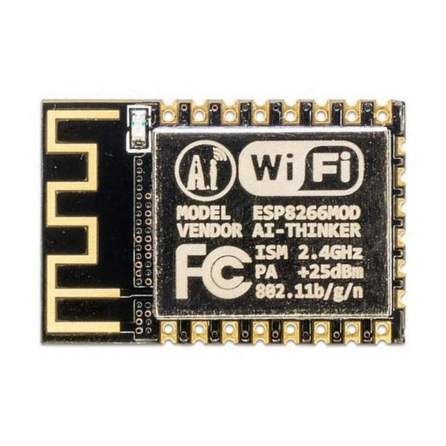
This Wi-Fi module is based on the popular ESP8266 chip. The module is FCC and CE certified and RoHS compliant.
Fully compatible with ESP-12E. 13 GPIO pins, 1 analog input, 4 MB flash memory.
This e-book (pdf), a software-only follow up to the best-selling Elektor Visual Studio C# range of books, is aimed at Engineers, Scientists and Enthusiasts who want to learn about the C# language and development environment.
It covers steps from installation, the .NET framework and object oriented programming, through to more advanced concepts including database applications, threading and multi-tasking, internet/network communications and writing DLLs. The DirectX chapters also include video capture. The e-book concludes with several chapters on writing Android applications in C# using the Xamarin add-on.
This e-book is based on the Visual Studio 2015 development environment and latest C# additions including WPF applications, LINQ queries, Charts and new commands such as await and async. The latest Visual Studio debugging features (PerfTips, Diagnostic Tool window and IntellTrace) are covered. Finally, the Android chapters include GPS, E-mail and SMS applications.
Additionally, the e-book provides free on-line access to extensive, well-documented examples — in a try for yourself style — together with links to the author’s videos, guiding you through the necessary steps to get the expected results.
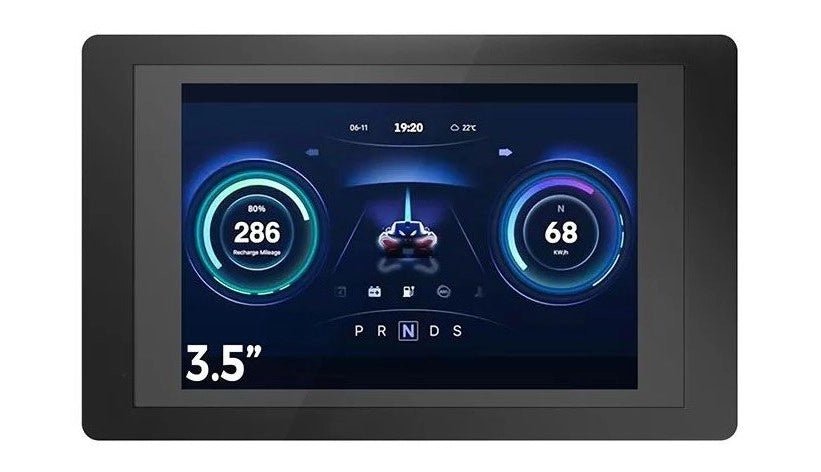
Introducing the Elecrow ESP32 Terminal, a revolutionary handheld device engineered to elevate your projects to new heights. Boasting a 3.5″ 480 × 320 TFT capacitive...
,
by Clemens Valens
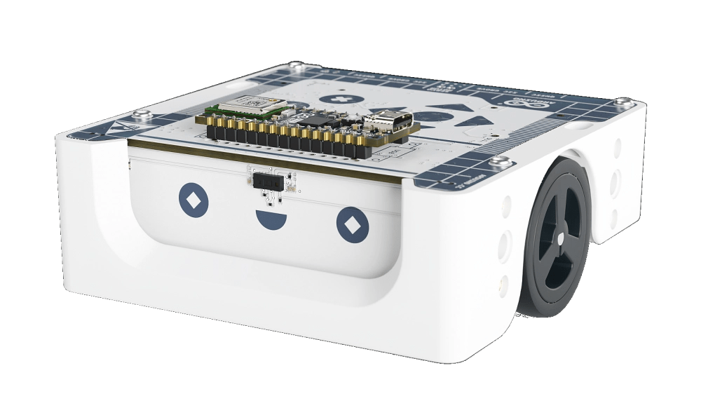
Inspiring the Next Generation with Arduino Alvik
In our rapidly evolving, technology-driven society, the demand for technicians, engineers, and developers continues to rise. Addressing the challenge of recruiting and training these essential...
,
by Saad Imtiaz
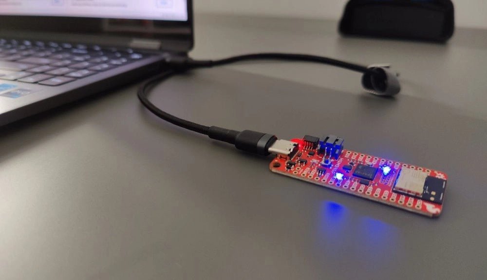
SparkFun Thing Plus Matter (MGM240P): A Versatile Matter-Based IoT Development Board (Review)
The SparkFun Thing Plus Matter (MGM240P) is a versatile and feature-rich development board designed for creating Matter-based IoT devices. Matter, formerly known as Project CHIP...